My 50 HURTS SubKick. MUAHAHA

wsabol

Gold Member
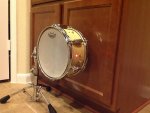
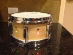
I built this subkick, and designed some special modifications of my own to make it.. more awesome.

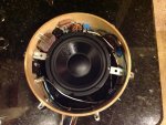
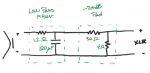
I used a 6.5" woofer, and installed a 20 dB pad.

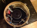
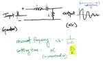
The major modification I integrated in this microphone is an RLC circuit. These circuits behave like a mass on a spring (or a drum haha): if you excite it, it gives an oscillation decay. You can design to ciruit such that this decay behavior has a specific frequency and sustain (decay time). I designed this one to decay at 50 Hz. I setup a multi-position switch and connected different resistors to it so you can choose a decay time.

It sort of behaves like a trigger, but it could not be less like a trigger. Its all completely analog, no power source or anything like that at all.

I think it can be useful to supplement the kick sound with subfrequency decay. I don't know if it'll be as prominent as say an 808 kick sound, but that's the idea. The more I think about it, the more I think 50 Hz may be too low, but only time will tell.

There are three switches, each with an LED indicator to show when it is on. The first switch turns the whole system on/off, the second engages the pad, and the third engages the oscillator.

I'm excited to try it out. I'll try to get some sound files up as soon as I can.

Let me know what you think!
 

Attachments

  • photo 4.JPG
    photo 4.JPG
    110.5 KB · Views: 758
  • photo 3.JPG
    photo 3.JPG
    119.5 KB · Views: 732
  • photo 1.JPG
    photo 1.JPG
    135.8 KB · Views: 886
  • photo 2.JPG
    photo 2.JPG
    132.6 KB · Views: 1,346
Oh I get it 50 hertz, not hurts as in it so low it hurts. Cool
 
Here is a sound file of just the normal subkick operation.

Specs: 20x14 kick, Shure Beta52a in the port hole & subkick. Those are the only mics. No eq/processing. First you'll hear it without the subkick, then the same clip with it in the mix

I first need to figure out if my whole 50 Hz thing even works - in theory in should, but yea. I'll try to get that up soon.

https://soundcloud.com/wsabol39/subkick-operation
 
Why 50 hz? The BETA 52 will go lower than that.

Isn't the whole idea of a sub kick is to get down to 20 hz?
 
And a 6.5'' woofer is rather on the small end. I'd go for bigger sizes for lower frequency.
Looks very tidy!
 
When you get into larger woofers, yes, they will capture lower frequencies, but in an exceedingly unnatural sounding way..

We've all heard Andy extole the virtues of the strong fundamental tone - Well when I think about the purpose of a subkick, its more for capturing the fundamental note and body of the drum, rather than just the lowest frequencies possible. General consensus is that 6"-8" is the sweet spot for actually capturing the natural fundamental notes of a kick drum. 6.5" is what Yamaha uses - that's a good enough reason for me.

50 Hz seemed like a decent middle ground, but I'll have to elaborate on that later after I've played with it some more.
 
Well when I think about the purpose of a subkick, its more for capturing the fundamental note and body of the drum, rather than just the lowest frequencies possible.

Ummmm, not me. A sub kick to means down to 20 hz and below and flatter in that area. Again the BETA 52 is rated down to 20hz.
 
Ummmm, not me. A sub kick to means down to 20 hz and below and flatter in that area. Again the BETA 52 is rated down to 20hz.

Well, good luck hearing any of that, let alone playing it back through any modest PA. And good luck finding mixing software that'll process those frequencies, let alone a mixing engineer that won't filter all that out anyway.

I think you might be reading too much into the name of this device. Listen to any subkick review video on youtube or eslewhere, those frequencies it picks up are audible and far above 20 Hz.

Regardless, just because a Beta52 is rated down to 20 Hz doesn't mean there are 20 Hz frequencies to pick up. The frequency rating also doesn't account for the diaphragm size and the natural dynamic response of the diaphragm. Standard kick mics are designed to capture more low frequency, yes, but they also need to capture 1000 Hz and above just as well. Subkicks are designed for only the lows, and that factors in to what gets recorded.
 
Last edited:
Update.

So, the crazy 50 Hurts oscillator thingy doesn't really work they way I wanted it too. The bass drum's response isn't strictly an impulse, in fact you get a few wavelengths of fundamental. Long story short, it behaves as a band pass filter centered around 50Hz, rather than what I was going for..

no big deal really, it just gives me a second chance to do something cool with this stuff. So here we go.. First off some anecdotes:

- I brought it to a large gig and had the sound guy hook it up in their house sound system. He said there is a lot nasty 500 Hz stuff in signal. General consensus was that with all huge subwoofers and speakers they have there, the subkick didn't add much, but would be good in the studio. Also, this guy had never used one of these before, and probably gotten more out of it and had more to say had me been familiar with the Yamaha version.

- In making that sound file I posted, I noticed that I was getting some phase cancellation between the two kick mics - inverting the phase on the subkick gave a better sound. I went back to check for the muddy nastiness that the sound guy mentioned to me, and sure enough its there. Most of the response comes from ~150Hz and below, but picked up a lot of everything.

The new idea is a low pass filter to replace that crap that doesn't work, and to add a phase inverter. I want to be able to use what I have so, the cut off frequency on the low-pass will be ~250Hz.

Schematic is below. The switches just make it so I can bypass either the filter, the pad, or both. I didn't draw the switches in there, because it gets kind messy, but hopefully you get the idea.

Feel free to ask questions.
 

Attachments

  • Capture.PNG
    Capture.PNG
    56 KB · Views: 990
Last edited:
How did you arrive at the component values? Specifically, why are you using such a small R/large C combo? I don't know how much wiring you have or what gauge it is but you could conceivably have over an Ohm just from that. For a 500 uF cap, your only reasonable cost choice is a polarized aluminum electrolytic which are among the lower performing caps you can get.

Also, I don't know what you were using for the 50 Hz resonant filter but you'd need a very high Q to get significant ringing (resonance) out of it. I'm not sure you'd like the sound of it anyway. In any event, if you post the circuit values and component specs (particularly the inductor) I'd be happy to crosscheck it.

Let me attach a schematic for the original design that incorporated the inductor.

Yes, thats a huge inductor. And yea, it had to be huge to get any appreciable sustain, and I'll also grant you that the signal was kinda weird when only that second order filter was engaged - not in conjunction with the pad.

The "Q", or sustain, I planned on controlling with that 0.17-2 Ohm "potentiometer". I had the worse time find a real potentiometer with these low resistances, so fashioned a multi-position switch with various resistance values from 0.17 Ohms to 2 Ohms at each position. It was awkward to say the least, haha

That inductor is 500W, 16 AWG, with an internal resistance of only 0.558 Ohms.
http://www.parts-express.com/erse-super-q-20mh-16-awg-500w-inductor-crossover-coil--266-960

That capacitor is a 100V Electrolytic Non-Polarized Crossover Capacitor..
http://www.parts-express.com/500uf-100v-electrolytic-non-polarized-crossover-capacitor--027-378

and I'm using 16 gauge wire.. im pretty positive.. regardless, I fairly certain I should have more than 0.1 ohms in wire around the circuits, and thats generous, especially now that I'm removing the pot and the L.

In an effort not to have to order new parts, I recycled the capacitor in this second edition, with a simple low pass filter.

I'm very happy you are challenging me on these points of parts specification. I know Kirchhoff's laws, Laplace's transforms, and Bode plots, but that's where my electronics knowledge ends. I welcome anything you to say about how I can make this better - don't hold back. Thanks.
 

Attachments

  • Capture2.PNG
    Capture2.PNG
    51.3 KB · Views: 450
Last edited:
First, if the coil resistance is a little over half an ohm you're never going to get a decent Q with these other resistance values. And then there's the ESR of the capacitor to knock it even lower. Also if you're really looking for it to ring, I think you might want to look at a parallel resonant circuit instead of series resonant. You could incorporate the pad as part of it, too. But the thing that really has me curious is why you chose such small R values to begin with. L and C scale in the most unfortunate manner when you do that. Why single digit R values instead of tens or hundreds of ohms? If anything, since you're looking for resonance, it seems a higher load impedance would be desired because you'd have less damping of the loudspeaker (i.e., it would exaggerate its own resonance frequency, so simply choose one with an Fs around 50Hz or so).

Do you have access to an oscilloscope? If so, try this little test. Run a scope probe to your loudspeaker's terminals and then tap the cone. You'll see an appropriate signal on the scope. Now do the same thing but also strap a small value resistor across the loudspeaker terminals (like an ohm or so). Tap it again. The signal will be smaller but it won't ring as much.
 
See the diagram below. This is how its works, and how expected it to work in practice, but like I said, the bass drum/diaphragm doesn't make for a very good impulse.

- The bass drum is the impulse - the input. The output to the board is what I wanted to augment.

- Think about the case with no resistance: the LC in series will oscillate forever - a perfect sinusoid. Resistors are like moongel, the add damping by leeching energy out of the system.

- The settling time (sustain/resonance) is dependant on the resistance (total, including the internal resistance of the coil) and the inductance such that a higher inductance and lower resistance increases sustain. If I used a 100 Ohm resistor in that circuit, the settling time would be 0.001 seconds (boo).. On the other hand, I could offset that by getting a 2 H inductor. But those mega huge inductors are largely unattainable.


Hence, my chooses, and maybe my predicament. { EDIT: sorry, that w_n (resonant frequency) formula should be squared, my bad --- (w_n)^2 = 1/(LC) }
 

Attachments

  • Capture3.PNG
    Capture3.PNG
    83.1 KB · Views: 449
Last edited:
Sorry, my bad, I should have explained. In meat space I'm a college professor, electrical engineering. My specialty is audio. I understand how all of this is supposed to work. My question is why did you decide to go with such a low resistance value? Did you get these values from somewhere else, another person's design, out of a book,...? It's possible to make a 50 Hz resonant filter with much more practical values.

Again, not 100% sure that's really what you want unless you're looking for a very specific sort of artificial effect. That part is none of my business though!
 
Bump. It's been quite some time since I've been around the forums... I haven't been able to play drums for ~16 months, so I've filled that time with learning about audio (I'm active on Head-Fi these days, budding EE myself)... I just wanted to say this is a super neat project, and it's really cool to see you share this!
P.S. I'd love to take a class from ya, Prof!
 
Well, good luck hearing any of that, let alone playing it back through any modest PA. And good luck finding mixing software that'll process those frequencies, let alone a mixing engineer that won't filter all that out anyway.

I think you might be reading too much into the name of this device. Listen to any subkick review video on youtube or eslewhere, those frequencies it picks up are audible and far above 20 Hz.

Regardless, just because a Beta52 is rated down to 20 Hz doesn't mean there are 20 Hz frequencies to pick up. The frequency rating also doesn't account for the diaphragm size and the natural dynamic response of the diaphragm. Standard kick mics are designed to capture more low frequency, yes, but they also need to capture 1000 Hz and above just as well. Subkicks are designed for only the lows, and that factors in to what gets recorded.

Spoken like a true engineer. lol

Most engineers will filter that out so fast to add head room its pointless to capture in the first place.
 
Back
Top